AGV and AMR Steering Drive Wheel Sizing: Scrub Torque, Tilting Moments, Slew Ring Bearings, and Steering Motor Gear Ratio Calculations
Size AGV steering drive wheels: calculate zero-speed scrub torque, tilting moments, slew bearing capacity and steering gear ratios with sizing equations.
For AGV and AMR steering drive wheels, sizing calculations must account for zero-speed scrub torque, dynamic tilting moments under emergency braking, slewing ring bearing combined loads, and two-stage steering gear reductions. Sizing a steering actuator purely on rolling resistance or static payload can underestimate peak torque, bearing loads and positioning error. A steering drive wheel is both a heavy-payload thrust bearing and a precision rotary servo axis.
This engineering guide provides actionable sizing formulas, load-transfer estimates, a six-scenario calculation matrix, slewing bearing topology trade-offs, and an OEM procurement checklist for robotics hardware architects and procurement managers worldwide.
For chassis-level layout comparisons, see our guide on Horizontal vs. Vertical AGV Drive Wheels. If you are evaluating drivetrain reduction technologies, consult Planetary vs. Cycloidal Gearboxes for AGV and AMR Drive Wheels. For brake sizing and verification context, review AGV Drive Wheel Electromagnetic Brakes: Holding vs. Dynamic Braking and ISO 3691-4 Integration.
Scope and engineering assumptions — reviewed 2026-11-07: The formulas, baseline calculation tables, and worked sizing examples below represent reproducible analytical models based on industrial vehicle mechanics. They use illustrative inputs for center-pivot polyurethane wheels on clean, dry industrial floors; they are not measured tire data or validated product ratings. The intended audience is AGV/AMR chassis engineers and OEM buyers preparing a supplier shortlist, rather than a vehicle safety approval. Specific tire compound formulations, wet or oily floors, mechanical compliance, and custom supplier gearboxes require physical verification and matched supplier datasheets.
Finalizing your mobile robot powertrain specifications? Submit your wheel-load envelope and duty cycle for a technical RFQ or evaluate catalog steering assemblies at our AGV Forklift Steering Drive Wheel product page.
1. The Physics of Steering Drive Units: Beyond Rolling Resistance
A steerable traction drive unit integrates two distinct mechanical drivetrains into a single compact subassembly:
- The Traction Powertrain: Motor, primary speed reducer (planetary, cycloidal, or bevel-helical), brake, and wheel hub providing linear tractive thrust (
F_traction). - The Steering Powertrain: Slewing ring bearing or turntable, secondary steering gearhead, steering pinion, and absolute feedback sensor providing rotary positioning (
θ_steer) around the vertical axis.
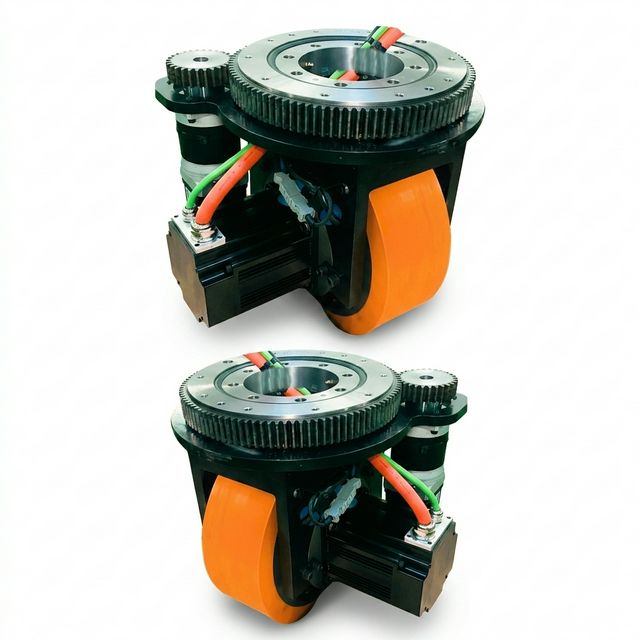
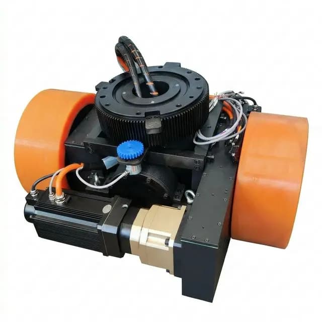
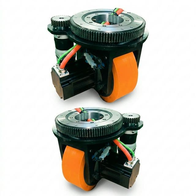
Figure 1: Integrated motorized AGV forklift steering drive wheel assembly with upper slewing bearing turntable interface and dedicated steering actuator.
A traction calculation alone does not establish steering capability. Review the steering axis separately because its load path, reduction ratio and motion cycle differ from those of the traction axis.
When an AGV operates in confined warehouse aisles, it frequently performs zero-speed pivot steering: turning the drive wheel while the vehicle remains stationary before initiating forward travel. At zero forward velocity (v = 0), the tire contact patch cannot roll through an arc. Instead, the polyurethane elastomer must physically twist and scrub against the floor surface under the applied normal wheel load.
If the steering motor and gearhead were selected assuming rolling steering resistance, the required scrub torque may exceed the motor's peak torque rating (T_peak). Repeated overloads can trigger current limits or thermal trips and can overload the gearbox or pinion connection.
2. Mathematical Derivation of Zero-Speed Scrub Torque (T_scrub)
When the drive wheel pivots around a vertical axis passing through the center of its contact patch, each differential area element dA on the floor contact surface generates a frictional shear resistance force dF_f = μ_s · p · dA, where μ_s is the static scrub friction coefficient and p is the local contact pressure.
A. Concentric Circular Contact Model
For a drive wheel with zero kingpin offset (the vertical steering axis coincides with the centroid of the contact patch), assuming an equivalent circular contact patch of radius a under uniform pressure distribution:
p = F_z / (pi * a²)Integrating the torque contribution of all concentric differential rings from radius r = 0 to r = a:
T_scrub = integral_0^a [ r * (mu_s * p) * (2 * pi * r) ] dr
T_scrub = 2 * pi * mu_s * p * integral_0^a [ r² ] dr
T_scrub = 2 * pi * mu_s * [ F_z / (pi * a²) ] * [ a^3 / 3 ]
T_scrub = (2 / 3) * mu_s * F_z * a
Where:
T_scrub: Zero-speed steering scrub torque (Nm).μ_s: Assumed limiting tire-to-floor friction coefficient. The examples use 0.65 for sensitivity screening, not a validated value for any Shore hardness or floor finish. Measure the intended tire and floor combination, including contamination and temperature.F_z: Normal vertical load acting on the single drive wheel (N).a: Radius of the equivalent circular footprint (m), obtained from an assumed or measured contact area asa = sqrt(A_contact / pi). Equal area does not preserve the friction moment of every footprint shape. Do not infer this radius from tread width alone. The model assumes uniform pressure and fully mobilized friction; elastomer compliance and breakaway hysteresis require physical checks.
B. Rectangular Contact Patch Formulation
For a rectangular footprint with width w and contact length l_c, use the distance from each area element to the steering pivot. A polar second moment of area is not the friction moment arm. Under uniform pressure and fully mobilized friction:
T_scrub = mu_s * F_z * r_eff
r_eff = (1 / (w * l_c)) * integral_A sqrt(x² + y²) dA
Here x and y are measured from a centered pivot. Numerical integration over the footprint provides a reproducible estimate; measured pressure distribution can replace the uniform-pressure assumption. For a square of side w, this integral gives r_eff ≈ 0.3826 * w, which is a useful independent check on a spreadsheet implementation.
C. Influence of Steering Axis Offset (e_offset)
For an offset pivot, evaluate the same integral using distances to the actual steering axis, for example sqrt((x - e_x)² + (y - e_y)²). Do not add a second friction term to the centered result without checking whether it counts the same tire force twice.
An external horizontal force acting away from the steering axis also creates a yaw torque given by the vertical component of r × F. Its sign depends on force direction and offset. Specify both longitudinal trail and lateral offset in the RFQ, then check steering in both directions. An allowable offset must come from the actual torque and packaging budgets, rather than a universal millimeter limit.
3. Dynamic Tilting Moments (M_k) and Slew Bearing Equivalent Load
The slewing bearing transfers the wheel reaction to the chassis. Its load envelope includes axial force, radial force and overturning moment; the governing limit depends on the bearing, support structure and operating case.
A. Emergency Deceleration and Load Transfer
ISO 3691-4:2023 covers safety requirements and verification for driverless industrial trucks and their systems. Its public abstract does not establish a universal deceleration, steering speed or encoder architecture. The numerical cases below are engineering assumptions, not values prescribed by that standard.
Determine total vehicle braking demand from F_brake,total = m_vehicle * a_decel, then allocate it to the wheels using the actual brake arrangement, traction limits and control strategy. A wheel supporting one quarter of the weight need not supply one quarter of the braking force. A holding brake must have a specific dynamic stopping rating before being used to arrest motion.
For a simplified level-ground, two-support vehicle with a rigid chassis, quasi-static forward load transfer is:
Delta_Fz = m_vehicle * a_decel * h_CG / L
Fz_front = Fz_front,static + Delta_Fz
Fz_rear  = Fz_rear,static - Delta_Fz
h_CG is the loaded center-of-gravity height and L the support spacing along travel. Suspension, additional supports, mast position and pitch dynamics require a more complete model. Check loaded and unloaded vehicles because either can govern wheel unloading or adhesion.
At one wheel, abs(F_x) <= mu_brake * F_z is a straight-line adhesion bound. Simultaneous cornering consumes part of that friction capacity. The horizontal force acts below the slewing bearing and produces:
H_pivot = R_wheel + H_housing
M_k,brake = F_x * H_pivot
For a Ø 300 mm wheel with R_wheel = 0.15 m and H_housing = 0.27 m, H_pivot = 0.42 m. An independently assumed braking force of 3,600 N gives M_k,brake = 1,512 Nm. This is a moment at the bearing, not steering-axis motor torque. Add the vector contributions of lateral force, eccentric vertical load and other applied moments for each load case.
B. Slewing Bearing Combined-Load Evaluation
Use the selected bearing's calculation method. Rothe Erde's bearing-selection guidance evaluates application-factored load combinations against static, bolt and service-life curves. Its coefficients and exceptions depend on bearing series; a universal axial-equivalent formula cannot replace that selection procedure.
Send the supplier simultaneous F_a, F_r and M_k values, their directions and their occurrence frequencies. If a catalog defines an equivalent axial load, use its factors, diameter definition, units and validity range. Do not carry an equivalent-load coefficient from one bearing family into another.
C. Static Margin, Mounting and Service Life
A scalar check such as C_0a / F_a,eq is meaningful only when the catalog defines those quantities for that load case. Agree the required application factors with the supplier, including floor joints, braking peaks and handling shocks; no single ratio guarantees freedom from indentation.
Ask for separate checks of raceway capacity, fastening bolts, mounting-plate stiffness, gear teeth and operating life. State preload, lubrication, seal friction and oscillation angles as well as load magnitude. A bearing can meet a static load limit and still have unsuitable deflection or wear behavior in repeated short-angle steering duty.
4. Engineering Calculation Matrix: 6 AGV Load Classes
The table below is an analytical sensitivity comparison across six illustrative wheel-load scenarios. It is not a standardized AGV classification or a catalog capacity table. Wheel dimensions and footprint radii are assumed independently; they do not establish a tire load rating.
Assumptions applied:
mu_s = 0.65, centered pivot, uniform circular footprint and fully mobilized friction.g = 9.81 m/s²and assumed decelerationa_decel = 2.0 m/s²; neither is a selected vehicle's verified stopping performance.- For this table only, braking force is allocated in proportion to wheel load:
F_x = (F_z / g) * a_decel. Actual brake distribution must replace this assumption. T_scrub = (2/3) * mu_s * F_z * a;M_k,brake = F_x * H_pivot. Values are rounded after calculation.D_pitchis a candidate raceway dimension for the supplier inquiry, not a capacity rating.
| Illustrative Scenario | Wheel Size (Dia × Width) | Wheel Load F_z (N) | Assumed Radius a (m) | Scrub Torque T_scrub (Nm) | Pivot Height H_pivot (m) | Braking Force F_x (N) | Braking Moment M_k (Nm) | Candidate D_pitch (m) |
|---|---|---|---|---|---|---|---|---|
| 1: Light AMR / Sorting | Ø 150 × 50 mm | 2,500 | 0.025 | 27.1 | 0.22 | 509.7 | 112.1 | 0.160 |
| 2: Warehouse AMR | Ø 200 × 65 mm | 5,000 | 0.035 | 75.8 | 0.28 | 1,019.4 | 285.4 | 0.200 |
| 3: Pallet Jack / Tugger | Ø 250 × 80 mm | 10,000 | 0.045 | 195.0 | 0.35 | 2,038.7 | 713.6 | 0.250 |
| 4: Counterbalance AGV Forklift | Ø 300 × 100 mm | 18,000 | 0.055 | 429.0 | 0.42 | 3,669.7 | 1,541.3 | 0.300 |
| 5: Heavy Reach Truck AGV | Ø 350 × 120 mm | 30,000 | 0.065 | 845.0 | 0.48 | 6,116.2 | 2,935.8 | 0.350 |
| 6: Heavy Industrial Transporter | Ø 400 × 150 mm | 50,000 | 0.080 | 1,733.3 | 0.55 | 10,193.7 | 5,606.5 | 0.420 |
Sizing insights from the matrix:
- Scenario 4 gives 429 Nm of scrub torque. A 2 Nm motor through a 30:1 reducer delivers at most 60 Nm before losses, so that combination cannot meet this assumed stationary steering load without a further reduction stage.
- Scenario 6 gives 5.61 kNm of braking-induced bearing moment. Submit this together with the 50 kN axial reaction and 10.19 kN radial force to the bearing supplier. These are simultaneous loads, not quantities to compare separately with unrelated maximum ratings.
- Scrub torque scales linearly with the assumed coefficient and radius. For scenario 3, raising
mu_sfrom 0.65 to 0.80 raises the estimate from 195 Nm to 240 Nm. A measured footprint and friction envelope are more useful than extra precision in the arithmetic.
If your vehicle payload or floor friction exceeds these baselines, review our heavy-duty options on the Heavy Load Forklift AGV Wheel Selector.
5. Slewing Bearing Topology Selection: Four-Point Ball vs. Crossed-Roller vs. Twin Tapered Kingpin
Selecting the correct internal bearing architecture governs the steering unit's vertical envelope, tilting stiffness, backlash resistance, and service lifetime.
The comparison below is a shortlist framework, not a dimensional or price specification. Schaeffler INA Catalogue 404 distinguishes four-point contact and crossed-roller designs and provides series-specific selection and installation information. Compare actual candidate drawings and load data before choosing a topology.
| Bearing or Drive Architecture | Selection Reason | Main Trade-off | Supplier Evidence to Request |
|---|---|---|---|
| Single-Row Four-Point Contact Ball Ring | Compact combined-load support | Clearance and deflection may limit precision | Combined-load curves, clearance and installed deflection |
| Single-Row Crossed-Roller Ring | Candidate for preload and running accuracy | Preload makes mounting and friction important | Preload class, stiffness data and mounting limits |
| Twin Tapered Roller Kingpin Bearings | Bearing spacing can resist overturning moment | Needs axial space and a designed preload arrangement | Load split, span, fits and preload procedure |
| Double-Row Ball Ring | Alternative combined-load arrangement | Envelope and load sharing depend on design | Load envelope, installed height and friction torque |
| Three-Row Roller Ring | Separate load paths can suit large modules | Packaging and mass may be excessive | Actual load curves, mass and connection design |
| Enclosed Worm Slew Drive | Packaged bearing and reduction assembly | Efficiency, backlash and slew speed vary | Reversing duty, thermal rating and backdrivability |
| Direct-Drive Rotary Torque Motor | Removes reduction-gear backlash | Bearing and motor thermal sizing remain necessary | Output torque-speed curve and integrated bearing limits |
The last two rows describe drive architectures, not rolling-element types. Neither self-locking behavior nor an integrated enclosure establishes a safety holding function. For tall masts, compare total chassis-and-bearing angular deflection: tip displacement ≈ mast height * tilt angle in radians. At 10 m height, 1 mrad gives 10 mm of displacement; 1 microradian gives only 0.01 mm. Request stiffness under the real combined load rather than a universal percentage advantage for one bearing type.
6. Sizing the Steering Drivetrain: Gear Ratio and Motor Matching
The steering drivetrain must deliver both high peak torque (to overcome zero-speed scrub friction) and adequate angular slewing speed (ω_s).
A. Total Reduction Ratio (i_total)
In the illustrated steering head, reduction is divided across two stages:
- Primary Stage (
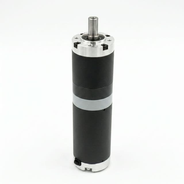
i_1): A compact coaxial planetary gearbox mounted to the steering servo motor (the example uses 15:1). - Secondary Stage (
i_2): An external spur pinion on the gearbox output shaft meshing directly with the integral teeth of the slewing ring bearing (i_2 = z_ring / z_pinion; the example uses 7:1).
The total kinematic reduction ratio is:
i_total = i_1 * i_2 = i_1 * (z_ring / z_pinion)For i_1 = 15 and a gear pair with z_pinion = 16, z_ring = 112:
i_2 = 112 / 16 = 7
i_total = 15 * 7 = 105:1
B. Angular Speed Matching (ω_steer)
Set the steering speed from the required maneuver. An average 90° rotation in one second corresponds to 90°/s, or 15 rpm; acceleration and deceleration require additional peak-speed allowance. This example uses 15 rpm as a steady operating point, not a universal navigation threshold.
With i_total = 105:1 and a desired steering speed of 90°/s (15 rpm):
n_motor = n_steer * i_total = 15 rpm * 105 = 1,575 rpmCompare 1,575 rpm with the selected motor's torque-speed curve at the minimum bus voltage. A 3,000 rpm nameplate alone does not establish available torque, efficiency or current at this operating point.
C. Motor Torque Verification
The steering motor must deliver sufficient torque to overcome zero-speed scrub resistance at the overall drivetrain mechanical efficiency eta_total = eta_planetary * eta_pinion-ring, assumed here as approximately 0.92 * 0.92 = 0.8464, rounded to 0.85 for the calculation:
T_motor,req = T_scrub / (i_total * eta_total)For scenario 3 (Pallet Jack / Tugger AGV, T_scrub = 195 Nm):
T_motor,req = 195 Nm / (105 * 0.85) = 2.18 NmThe 2.18 Nm result is a scrub-only estimate. Add output bearing/seal friction, cable resistance and J_output * alpha_steer before dividing by ratio and efficiency. Check gearbox peak duration, repeated-duty limits, pinion tooth force and output-shaft loads separately. The diagram's 3.8 Nm peak motor gives approximately 3.8 * 105 * 0.85 = 339 Nm at the turntable, conditional on the gearbox and drive limits.
Repeated steering needs a thermal check as well as a peak check:
T_motor,RMS = sqrt(sum(T_motor,j² * t_j) / sum(t_j))Ignoring other loads, 2.18 Nm during 50% of a cycle and zero torque for the rest gives about 1.54 Nm RMS. A 1.0 Nm continuous motor is therefore not established as adequate by a 3.0 Nm peak rating. The same simplified load at 10% duty gives about 0.69 Nm RMS. Validate the actual trajectory, cooling, low-speed current, ambient temperature and drive peak-current duration; these examples are screening arithmetic, not motor approval.
7. Steering Feedback and Functional Safety (ISO 3691-4 Integration)
Feedback must establish wheel orientation, measure output motion with adequate accuracy and support the vehicle's defined fault response. These are related but distinct requirements.
A. Referencing and Absolute Angle Feedback
An incremental encoder does not inherently retain position through loss of counter power. An E-stop does not necessarily erase its count if the encoder and controller remain powered. Determine whether motion can occur while counting is unavailable and how orientation is re-established afterward.
An output-side absolute encoder is a useful way to avoid a mechanical homing sweep at startup, provided its calibration, coupling and data validity are checked. A single-turn device may be sufficient for orientation within 360°. Multi-turn information is relevant if revolution count, limited cable winding or multi-revolution travel must be tracked; a slip ring does not by itself require a multi-turn encoder. Incremental sensing with a validated reference strategy can also be appropriate. Define a controlled recovery procedure before permitting motion in a constrained aisle.
B. Dual-Loop Control and Gear Mesh Backlash
Specify backlash at the steering output under a stated measurement torque, temperature and wear condition. For tangential clearance b at ring pitch radius r, the small-angle lost motion is approximately b / r radians. For example, 0.30 mm at 150 mm pitch radius is 0.002 rad, or about 0.115°; it is not a universal steering tolerance.
An output encoder lets the outer position loop observe actual steering motion while a motor encoder supports the inner velocity loop. This can compensate for some positioning error, but it does not remove physical clearance, compliance or the risk of oscillation. Tune both loops against the loaded mechanism and verify reversal response, docking accuracy and settling time.
C. Functional Safety and Steering-Angle Monitoring
If the vehicle uses steering angle to select protective scanner fields, an invalid angle can invalidate the intended protected area. Define the safety function, required integrity, detection time and fault response in the vehicle risk assessment and applicable requirements. Confirm the relevant edition of ISO 3691-4 and any associated control-system standards for the destination market.
Two ordinary encoders do not automatically create a validated safety architecture. A safety-rated encoder also does not certify the entire function: its mounting, power supply, communication, plausibility checks, controller logic and stopping response need evaluation. Request supplier safety documentation and diagnostic coverage appropriate to the chosen function. This guide does not establish a universal PL d / Category 3 requirement or demonstrate compliance for a particular vehicle.
8. Sizing Calculation Checklist for Engineering & OEM Buyers
Before releasing an RFQ for customized or catalog steering drive wheels, mechanical engineering and procurement teams should verify every parameter in the checklist below:
- 1. Wheel-load envelope: Record minimum and maximum vertical wheel loads, loaded/unloaded center of gravity, suspension behavior and transient load transfer.
- 2. Scrub torque: State the measured or assumed footprint, pivot offset and friction range. Check peak output torque in both steering directions, including acceleration and parasitic loads.
- 3. Bearing moments: Measure ground-to-raceway height and horizontal offsets. Combine braking, cornering and eccentric vertical forces for each credible simultaneous case.
- 4. Bearing acceptance: Obtain the supplier's combined-load calculation, application factors, bolt check and mounting-flatness limits for the exact part and support structure.
- 5. Steering motion and duty: Specify angle change, move time, acceleration, cycles per hour and dwell. Check motor RMS torque, minimum-voltage torque-speed limits and gearbox peak duration.
- 6. Angle reference: Define startup orientation validity, reference retention, sensor coupling checks and a controlled recovery procedure after loss of position.
- 7. Backlash budget: Specify output lost motion and loaded stiffness at defined conditions, then verify reversal behavior and docking accuracy after endurance cycling.
- 8. Lubrication and environment: Agree lubricant, relubrication interval, open-gear protection, temperature, contamination and inspection access. Match these to the actual duty cycle.
- 9. Safety and acceptance records: Identify any safety-related use of steering angle, required fault response and vehicle-level validation. Request traceable test conditions and results rather than relying on a generic compliance claim.
9. Frequently Asked Questions (FAQ)
Why do steering motors stall during zero-speed pivoting even when rated for vehicle turning?
At zero vehicle speed, the tire contact patch must twist and scrub against the floor. Rolling resistance alone does not describe that load. Estimate scrub torque from the contact pressure and pivot geometry, add bearing, seal, cable and acceleration torque, and check the motor and drive peak-current duration and repeated-cycle thermal limits.
How does emergency braking affect the steering slew ring bearing rating?
The horizontal braking force produces a tilting moment equal to that force multiplied by its height below the bearing. Combine this with axial load, radial load and any vertical-load eccentricity in the selected manufacturer's load-case method. Braking-force distribution and wheel-load transfer must be evaluated separately; supported weight alone does not determine braking force.
When should an AGV use a crossed-roller slewing bearing instead of a four-point contact ball bearing?
Shortlist a crossed-roller bearing when stiffness, preload and running accuracy are central to the design. Compare it with a four-point contact bearing using the actual load envelope, mounting tolerances, friction torque and supplier deflection data. Bearing type alone does not establish stiffness, shock capacity, service life or suitability for a high mast.
What target steering angular velocity is required for industrial AGV navigation?
Set the steering speed from the required angle change, available maneuver time, acceleration limits and vehicle controller. The worked example uses 90 degrees per second, equivalent to 15 rpm, as an assumed operating point. It is not a universal navigation requirement; validate tracking and stopping behavior on the intended vehicle.
Does an AGV steering axis need an absolute multi-turn encoder?
An output-side absolute encoder can provide wheel orientation after power-up without a mechanical homing sweep, subject to valid calibration and diagnostics. Single-turn sensing may be sufficient for orientation within one revolution. Multi-turn sensing is useful when revolution count or cable winding matters. An incremental system can also work with a verified reference strategy and a controlled homing procedure.
What parameters must an OEM provide in a steering drive wheel RFQ?
Provide minimum and maximum wheel loads, tire dimensions and compound, floor conditions, braking and cornering forces, pivot height and offset, steering angle and timing, duty cycle, allowable backlash, supply voltage, feedback interface and environment. Request matching bearing load curves, gearbox peak and continuous limits, motor thermal data and a documented acceptance test.
Summary & Technical Next Steps
Sizing an industrial AGV steering drive unit requires simultaneous structural and electro-mechanical verification:
- Never size the steering motor on rolling resistance: Always compute zero-speed contact patch scrub torque using a footprint model, such as
T_scrub = (2/3) * mu_s * F_z * afor the centered circular assumption. - Never size the slewing bearing on vertical payload alone: Compute braking load transfer and overturning moments (
M_k = F_x * H_pivot), then apply the exact bearing manufacturer's combined-load method. - Verify output-angle feedback: Establish orientation before vehicle motion, define reference-loss recovery and validate the loaded positioning loop. An output encoder observes backlash effects; it does not remove physical clearance.
Looking to evaluate pre-engineered or custom-built steering drive units? Explore technical specifications on our AGV Forklift Steering Drive Wheel product page, or contact our engineering team to review your vehicle load envelope and request CAD models.
Sources and Calculation Limits
Sources checked on 2026-11-07. The equations and scenario calculations above are analytical examples, not measured product performance, customer case studies or a compliance assessment. Revisit the assumptions when the tire, floor, vehicle layout, control duty or supplier part changes.
- ISO 3691-4:2023 — driverless industrial trucks and their systems. Supports the scope of vehicle safety requirements and verification. The public abstract does not substantiate specific stopping rates, steering speeds or performance levels used in a design; consult the applicable full requirements.
- Rothe Erde — technical basis for bearing selection. Supports supplier-specific combined-load selection, application factors and capacity curves. It is not a source for a universal equivalent-axial-load coefficient.
- Schaeffler INA — Slewing Rings, Catalogue 404. The introductory design comparison and engineering sections describe bearing families and installation considerations. This catalog is a design reference; confirm the current data for the exact candidate part.